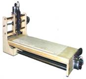
Stews CNC Router / 3D Printer
So
I decided to build a CNC Router to automate the creation of some printed
circuit boards I am interested in making.
Much
research on the internet…….
I
have come to the conclusion that a CNC router if built correctly could be used
as a 3D Printer, cool, I wanted one for a while now!
So
the first thing s I need to do is look at the different CNC designs and 3D
printer designs and come up with the best of both.
Requirements:
1. Most 3D printers cannot handle the
lateral forces required to move a CNC cutting head so I need to stick to the
simple CNC designs.
2. CNC routers move relatively slow
while 3D printers move fast, what is best?
3. Looking at accuracy I have runs on
my circuit boards down to 10 mils that I will need to cut.
4. I would also like to use my 3D
printer for some rather small and accurate designs so I need to keep that into
account
5. There are two type
of drive systems, belt and main screw. I need to determine which is best for my
application.
6. My stepper motors need to be able
to provide forces that would be required for a CNC router.
OK
let’s start looking at simple things I can buy now to get started:
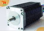
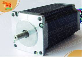
1. Stepper motors, NEMA23 428oz-in CNC stepper motor stepping motor/4.2A
Ok good start now what do I
need to control it??? Back to e-bay…
SO I need a brain for the XYZ
and motor control to connect to the PC, and drivers for the stepper motors. So many to choose from?
Options available:
Combined controller drivers:
Cost is low,
Separate Controller: More
selection,
What do I want?
You can get external
displays; this would be good for setup and any calibration that needs to be
done. So this is a nice to have option. Can I get it all?
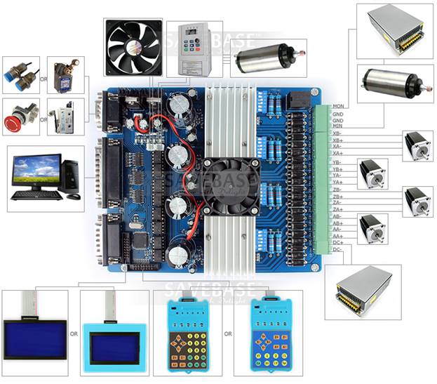
High Integrated 4Axis TOSHIBA
TB6600HG Stepper Motor Driver Nema17/Nema23/
This looks like a good choice
it includes the main board, display and keypad.
So from the diagram I need a
PS for the steper motors and one for the CNC motor
head as well as some other odds and ends.
So for the stepper motors it
recommends 36V PS for NEMA 23 motors so:
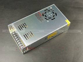
New 36V 10A 360W DC Regulated
Switching Power Supply CNC SM2
Looks good,
Add the CNC head as a kit:

AC110/220V CNC Kit M335
Stepper Motor Driver + 400W Spindle Motor + Power Supply
Ok now were moving along!
So my design will require a
frame with XYZ axis:
Back to the internet to
research:
Lots of good hobby pages:
hobbyrouterplans.com


So they all look pretty much
the same in basic design. They all use this main screw?
So with some research it
turns out the belt systems though fast tend to suffer from wear and tear
resulting in inaccuracies and do not stand up to some of the higher torque
levels.
Interesting tidbit I found
that the best way to see the accuracy of a CNC machine is to cut a circle. At
the points X &Y where a stepper motor reverses Direction you get backlash
causing inaccuracies in the cut. To compensate you need a loaded lead screw?
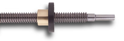
More research!
Ok lead loaded lead screws
are very expensive!! Need to see if I can make one?
So if you hold a bolt and
screw in your hand and try to move the nut without turning it you can feel a
very small movement! Backlash! Ok so how to compensate?
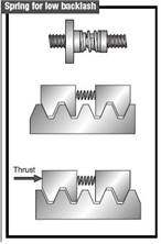

 What if I took two nutss and
put a spring between them forcing them outward against the threads?
What if I took two nutss and
put a spring between them forcing them outward against the threads?
 Start with a block: Add some brass chunks for
Nuts. Cut out the inside
Start with a block: Add some brass chunks for
Nuts. Cut out the inside
How do I get square cormers????
Back to the
Internet.
Need to use a tool to
basically force cut the corners..
So I need to make one:


Here it is assembled, one nut
locked in place and one movable under the spring.
Ok time to add the threaded
rod and see how it works:
Just like I imagined it, yes!
So the parts have started to
arrive first the stepper motors, then the PS and last the controller.
I’m going to need a housing
to go between the stepper motor and the main screw to link them together. Again
the cost to purchase one is not acceptable so I need to make some. I could use
a square tube and cut out the stepper motor on one end and the bearing for the
main screw on the other. Oh, I need to order a bearing and coupler as well,
back to e-bay.


Ok ordered them.
I also need some rods and
linear bearings to have my XYZ axis move along.


These look good, ordered.
So while I am waiting for the
parts lets look at 3D print heads.


So I need a heat sync to hold
the temp and melt the ABS plastic.
I need some force feed
system.
I need to cool the feed tube
between the force feed and the nozzle.
I need a heater and temp
sensor.
I think I can do better
building one myself than paying for a cheep one.
I like the metal cooling fins
design. So what do I need back to e-bay to see what I can order.


Some print
nozzles, A feed gear, a guide bearing, Heater, temperature sensor. And a small stepper motor to feed the ABS.

So I’m thinking something
like this with a better heat sync on the end, lets head
over to the local metal supply shop.

This looks good 1” aluminum
and 1” copper. Lets cut some
fins!


Well this sucks. The cut off
tool wavers on the lathe and I get a mess.
There has to be something
better, back to the internet.

So the best I can find is
examples of using a Dremel like tool on the mill to
cut the fins. I have some blades but I will need to make the tool holder.
Now I need a way to rote the
aluminum dowel off centered? I have a rotary table for the Mill.


I have a four tooth head for
the lathe, can I combine them?
Ok that worked with a little
modification:

Final result: Not too bad.
Some more parts are in, let’s
try to assemble them:


Stepper motor, a new housing
and lead screw, end bearing coupler and a face plate all done, not too bad.
Add the linear bearing the
slid rod and my new loaded bearing and we are finally getting somewhere.